

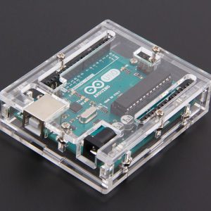
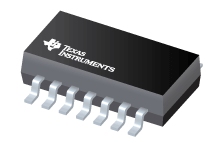
Arduino Pro Mini ATmega328 3.3V
The Arduino Pro Mini is intended for advanced users who require flexibility, low-cost, and small size. It comes with the minimum of components (no on-board USB or pin headers) to keep the cost down. Be sure to provide the correct power and use components whose operating voltage matches that of the board.
₹600.00
Arduino Pro Mini ATmega328 3.3V
The board comes without built-in USB circuitry, so an off-board USB-to-TTL serial convertor must be used to upload sketches. This can be a FTDI TTL-232R USB – TTL Level Serial Converter Cable for the 5V Arduino Mini Pro), or a FTDI TTL-232R-3V3 USB – TTL Level Serial Converter Cable. One quick way to connect these is by inserting a six-pin 0.1″ male pin header into the end of the FTDI cable or breakout board, and pressing it against the six hole programming header on the Mini Pro. If, however, you’re going to be uploading lots of sketches to your Pro Mini, you’ll probably want to solder some pins (male headers) to the holes.
The board can be powered through USB via the six-pin programming header, or from a regulated 5V (depending on the model) supply applied to the VCC pin or an unregulated supply on the RAW pin.
Any standard 0.1″ spaced header can be soldered to the holes on the Arduino Pro Mini. To use every pin requires two 12-pin headers, plus a six pin header for programming, if desired. Bare wire can also be soldered directly to the holes.
ATMEGA 328 Specifications :
- 131 Powerful Instructions – Most Single Clock Cycle Execution
- Up to 20 MIPS Throughput at 20 MHz
- Two 8-bit Timer/Counters with Separate Prescaler and Compare Mode
- One 16-bit Timer/Counter with Separate Prescaler, Compare Mode, and Capture Mode
- Real Time Counter with Separate Oscillator
- Six PWM Channels
- 8-channel 10-bit ADC in TQFP and QFN/MLF package
- Programmable Watchdog Timer with Separate On-chip Oscillator
- On-chip Analog Comparator
- 23 Programmable I/O Lines
Based on 0 reviews
Only logged in customers who have purchased this product may leave a review.
You may also like…
-
Sensors
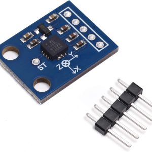
Accelerometer Sensor Module GY-61 ADXL335
✔ 3-Axis Sensing – Measures X, Y & Z-axis acceleration (±3g range)
✔ Analog Output – Simple interface with Arduino, ESP8266 & other microcontrollers
✔ Compact Design – Small PCB with easy-to-use breakout pins
✔ Low Power Consumption – Ideal for battery-powered projects
✔ Wide Compatibility – Works with Arduino, Raspberry Pi, ESP32 & moreSKU: n/a -


There are no reviews yet.